 |
 |
|
|
|||||||||
|
|
||||||||||
Card Reader In |
This reader is connection is essential for entering into the secure area. The connections are for clock and data readers. This include magnetic swipe readers and proximity readers with clock and data output. |
|||||||||
Card Reader Out ## |
Optional card reader for exiting the secure area.
The connections are for clock and data readers. This include magnetic swipe readers and proximity readers with clock and data output. |
|||||||||
Magnetic Door Contact |
This magnetic contact (closed when door closed) monitors the status of the door at all times. For proper function of the system this contact must be fitted. It is used to detect that a card holder has not only swiped their card, but also opened the door. ie. granted acces rather than simply swiping a valid card. |
|||||||||
Exit Button ## |
Optional device (push to make) that allows egress from the secure area. |
|||||||||
Lock Connection |
This relay controls the Electromechanical locking device. The terminals are NC, NO and C. (ie. a changeover relay).
For 12v dc locking devices you can use the 12v dc power supplying the controller, provided that the lock does not use more than 500mA MAXIMUM. |
|||||||||
Alarm Relay Connection |
Connect a sounder here for local alarm or use the relay to trigger another system eg CCTV control.You have a changeover relay connection. This relay will change state if either :
|
|||||||||
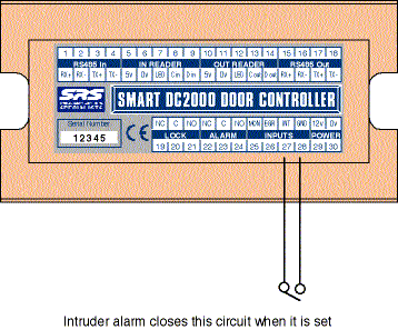
Intruder Alarm Connection |
If the door is the main entry door and you have an intruder alarm fitted, you may wish to make use the intruder alarm input. Making these connections will only allow access to 'Keyholders' when the intruder alarm is set. This is REGARDLESS of any access priviledges set (except Door in Free Access). |
|||||||||
| ## You would not require both these options on any one-door node. ie you would normally require a card reader OR and exit button |
||||||||||
Fig 4Components of a Smart Door Node |
|
|||||||||
Intruder Alarm Connection |
If the door is the main entry door and you have an intruder alarm fitted, you may wish to make use the intruder alarm input. Making these connections will only allow access to 'Keyholders' when the intruder alarm is set. This is REGARDLESS of any access priviledges set.
|
|||||||||
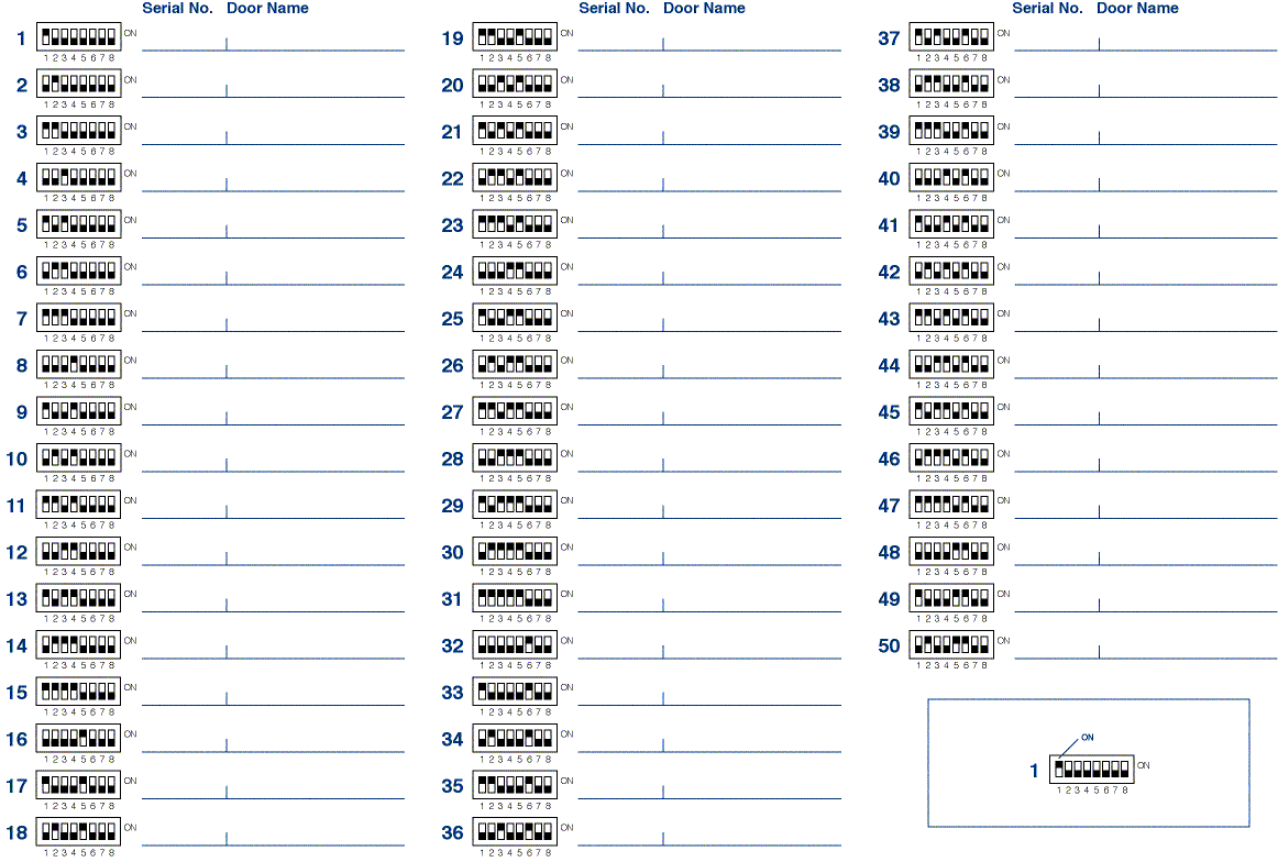
Setting the DC2000 DIP switches |
The basic rules of addressing are ,
|
|||||||||
Testing the Smart Door Node |
On completing the installation of a smart door node some basic tests can be carried out to establish operation prior to moving onto the next stage of installation. We refer to these tests as the, 'smart door node tests' and are detailed below. When all connections for a single SMART Door Node are installed the 12v dc power supply can be turned on. The DC2000 Door Controller is pre-pro-grammed with a lock release time of 7 seconds. Before proceeding you MUSTcheck the following:
If all is OK then remove power. Install and test the remaining SMART Door Nodes. After this has been complete we know that the control units are functioning correctly. We only now need to connect the network and test it. |
|||||||||
|
© Door Entry Direct Ltd |
||||||||||

